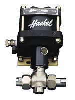
Pneumatic Driven Pumps

Haskel International has nearly 60 years of hydraulic and pneumatic engineering experience in the design and manufacture of air driven liquid pumps. Continuous investment in new machinery and technology keeps Haskel at the forefront of the field. We offer the most complete range of models in the industry measured for:
- Capability of ultimate pressure, flow or output horsepower.
- Compatibility with a variety of liquids.
Pressure and Flow on Demand
This guide will help you to pre-select the pump ideally suited for your application. If you have specific questions, however, we urge you to provide us with details of the duties you require from the pump, available air/gas drive pressure, and pressure/flow requirements, and we will recommend a model and any corresponding accessories.
Output Horsepower Rating
The pumps are categorized on their horsepower ratings (see pages 6-7). These are approximate and peak at 100 psi (7 bar), assuming adequate drive air, pressure and volume. Peak horsepower is at about 75% nominal ratio x air drive pressure, i.e. 100:1 pump @ 100 psi air drive peaks at 100 x 100 = 10000 x 0.75 psi = 7500 psi (517 bar) hydraulic pressure.
Double and Triple Air Head Pumps
Performance can be extended by stacking air pistons without changing the hydraulic piston. Haskel multi-head pumps consume less air than competitive single head pumps of the same area, as only one head is pressurized on the return stroke; e.g., on a 1.5 hp pump additional heads can raise performance to 2 hp. Double air head pumps are identified by the last digit 2 in the pump model number. Thus, a nominal 50:1 ratio pump with two air heads is described as a 52. Similarly, a triple air head pump is identified with a last digit 3. Thus, a 900 ratio pump with three air heads is described as a 903.
Operation
The pumps automatically reciprocate on a differential piston principle. A large piston driven by relatively low pressure drive acts directly upon a smaller hydraulic piston. The nominal ratio between piston sizes is indicated in the model coding and approximates to the maximum working pressure. The actual ratio is about 15% above nominal so that the pump continues to cycle when drive pressure equals nominal ratio. Initially, the pump will cycle at maximum speed acting as a transfer pump to pressurize downstream. It will cycle at a slower rate as the fluid meets resistance until it stalls at maximum output pressure. When a pressure drop downstream occurs, it will recycle as necessary in an effort to maintain maximum pressure. Stall pressure is achieved when the outlet pressure rises and offers more resistance to the reciprocating differential piston assembly. The piston assembly then stalls when the forces balance, e.g. when drive pressure x drive piston area equals outlet (stall) pressure x driven hydraulic plunger area. The pump design is sensitive to very small pressure drops due to the low frictional resistance of the large diameter drive piston and hydraulic piston seals.
Anatomy of a Pneumatic Driven Pump
- Drive Section - The piston, complete with “O” ring seal, operates in an epoxy filled, fiberglass wound barrel, the diameter of which is constant throughout a given series of pumps. Drive media forces the piston down on the compression stroke and raises it on the suction stroke (M series have a spring return). The piston is pre-lubricated during assembly and therefore no air line lubricator is necessary.
- Hydraulic Section/Check Valves - This is directly linked to the drive piston by the hydraulic piston, the bottom portion of which is in the hydraulic body. Outlet flow and pressure are determined by the area of the hydraulic piston head, its nominal ratio with the drive piston head, and drive pressure. On the down stroke, liquid in the hydraulic section is forced under compression through the outlet check valve. Fresh liquid is induced via the inlet check valve on the return stroke. These check valves control the flow of liquid through the hydraulic section. They are spring-loaded and have a very low cracking pressure, allowing maximum opening on the induction stroke. The pressure of hydraulic fluid on the down stroke closes the inlet check valve and acts against the spring to open the outlet check valve.
- Drive Cycling Valve - This is a pilot-operated, unbalanced, lightweight spool, which directs drive pressure, first to the top of the drive piston, and then to the underside to reciprocate the piston (cycle). It actuates via pilot valves at the top and the bottom of the stroke, which causes the unbalanced spool to shift and reciprocate the piston.
- Hydraulic Seal/Check Valves - This is one of the few wear parts. Its function is to allow the hydraulic piston to reciprocate without passing fluid into the drive section. The liquid, its pressure and its temperature determine seal specification. A distance piece can be incorporated between drive and hydraulic sections for complete contamination-free operation on most Haskel pumps.
Click here for more Product Details from
Haskel International, Inc....